I recently heard about the NAB's Technology Apprenticeship Program. Basically, this is a program for people starting out in broadcast engineering, or people with skills in other technical disciplines - "IT, digital technologies, ... or other related areas", as the website puts it - to get some hands-on experience in the field. Since that's the line of work I'm trying to get into, I applied, and I was accepted! So here's how my next few months are going to go:
April 9 - 14: I'll be flying out to Las Vegas (on NAB's dime, no less) to the NAB show. There are going to be several activities geared specifically for the apprenticeship program participants, (you know what? I'm going to say "apprentices" from now on. "apprenticeship program participants" is a mouthful) and we apprentices will be meeting with leaders in broadcast technology.
May 18 - 19: I'll be flying out to Silicon Valley for the http://www.radioink.com/ Convergence Conference.
June - July: I complete a two month paid internship at a TV or radio station. No idea what station yet.
Finally, in August, I go to DC for a week to work with NAB's Science and Technology Department to develop a presentation to be delivered via webcast at the end of my visit. If I'm permitted, I'll publish a link or something here.
I'm very excited about all of this. Not only is this going to be a really interesting and unique experience, but this is going to be a great start to my broadcast engineering career.
So stay tuned, Dear Reader, for more thrilling tales of broadcast engineering! ;)
Friday, March 18, 2011
Wednesday, March 16, 2011
Constructing a dummy load
A useful thing to have around is a dummy load. This allows you to tune a new radio (or modifications to an existing radio) without potentially damaging your radio (transmitting without a load connected can damage a transmitter) or causing interference.
Now, I could have bought myself a dummy load for thirty bucks or so. But where's the fun in that? I decided to build one instead, and I found a set of plans for one. Thanks to Ken Kemski, K4EAA for the plans.
To begin with, I went to Westlake Hardware to pick up a 1 qt. paint can and a sheet of aluminum. The original plans recommended brass, but aluminum was cheaper, so I went with that. Little did I know that aluminum is fiendishly difficult to solder with the 60/40 Sn/Pb stuff I have. After I discovered this, I went back to the hardware store and picked up some brass, which turned out to be much nicer to solder.
I then ordered a couple of banana plug posts, 20 3W (Watts)1 k&Omega (1 kΩ = 1000 Ohms); resistors, a 0.01 uF ceramic capacitor, and some BAV21 diodes from Mouser, per K4EAA's part list. For resistors, I went with Vishay metal film resistors. Of the resistors I examined, these had the flattest frequency response curve1.
So what's the point of all these bits? The can, obviously, is to hold everything. The resistors are to absorb the RF energy and turn it into heat. They'll be submerged in oil (some canola oil that I had laying around) to help dissipate that heat. The brass is to make a couple of plates that hold the resistors. The banana plugs, diodes, and capacitor are all for measuring your transmit power.
So to begin with, let's look at a schematic of this dummy load.
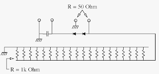
There are 20 1 kΩ resistors in parallel. This provides a total resistance of 50 Ω. As each resistor is rated for 3W of power, these resistors can safely dissipate 60 W of power without becoming damaged. Submerged in oil, they will be able to dissipate at least 100W, I expect, and probably a bit more.
You'll notice two sets of terminals in the schematic. One set has the capacitor between them, and is connected to one of the plates by two diodes. These terminals are meant for measuring the peak voltage (remember that radio frequency (RF) energy is alternating current (AC), and in AC, the voltage is always changing in both magnitude and direction) the connected transmitter puts out. The diodes ensure that only the positive side of the AC comes to the capacitor, and the capacitor charges up to your peak voltage. You can then determine your transmit power from your peak voltage 2.
The other set of terminals is where you connect the transmitter. You can use any connector you like for this - K4EAA uses a BNC; I use an SO-239. Next time I might use a BNC, though.
Now that we've got our schematic squared away, let's build the thing. I started out by making the brass plates that I was going to solder the resistors to. K4EAA (you'll notice a lot of hams will refer to each other by call sign, rather than given name. It's a thing.) cut his out with tin snips. That seems like an excellent idea, but I lack tin snips, and I didn't want to shell out for a pair, so I decided to repeatedly bend the metal back and forth until the metal at the bend fatigued and broke. It's not nearly as elegant, and it's not as pretty, but it works. To make the octagon shape (so that the plates would fit in the paint can) I cut off the corners using diagonal wire cutters.
Next, I divided each plate into twenty sections using a Sharpie, and made an "X" near the edge of each section. I was going for a point that was as far as possible from the center of the plate while maintaining maximum separation from its neighboring points. This was fairly inexact, and I'm sure that if I had taken the time to model this mathematically, I could have found a more optimum resistor spacing. But that level of precision is not really called for here - it's a dummy load, and it's meant to absorb RF. If one resistor gets slightly hotter than its neighbors, the oil is going to go a long way towards mitigating that fact.
Now that I had my "X"'s marked, it was time to start poking holes. I did this with a circular (well, tapered cylinder) needle file I had laying around, and it was pretty easy. Just put some pressure on the file and once it's punctured the metal, rotate it a little bit to widen the hole.

Once the holes were poked, it was time to start attaching resistors. And here I may have made a mistake. Figuring that I wanted the maximum spacing between the plates, to allow for maximum heat dissipation, I only put each resistor through its hole a little bit, i.e., I left long leads on the resistors. I figured that since this was a dummy load, any stray reactance wouldn't matter. I may have incorrect in that assumption, as I'll explain later. At any rate, I soldered all twenty resistors to the bottom plate. To maximize conductivity between the resistor lead and plate, I soldered to both the top and bottom of the plate.
K4EAA recommends, when attaching the top plate, that you cut one resistor lead down to your minimum lead length, then cut the rest progressively longer. That way you can insert the leads a few at a time into the top plate. Still operating under the assumption that I wanted maximum spacing between the plates, and feeling like a bit of a mechanical challenge, I decided against that, and instead managed to get all twenty resistors into the holes. It took quite a bit of fiddling. :) After I got all twenty resistors in, I soldered them to the plate, again top and bottom.

I also needed a hole in the top plate for the back of the SO-239 to go into. My original plan was to push the SO-239 through the hole you see here and attach it via the included mounting nut. This did not prove feasible, however, as the banana plugs got in the way. So instead I widened the hole a bit to maintain a space for the center conductor to go through.

Here you see the hole that the center conductor from the SO-239 will connect to.

I wanted the dummy load to be grounded to the chassis - in this case the paint can. It seemed the simplest way to ensure that both the shield of the SO-239 and the black banana post were at the same ground potential. And when I poked holes (again with the needle file and, in the case of the SO-239, my small wire clippers) in the top of the can, the black banana post had an excellent connection to the can lid. The SO-239, however, didn't have as good of a connection, so I sanded away the coating on the bottom of the lid under the hole for the SO-239. That worked much better. The twisted copper wire you see here attached to the shield of the SO-239 ended up connected to the top brass plate. This ensured both a good mechanical connection from the plates to the can, and also a good electrical connection between the top plate and the can (and thus the shield of the SO-239 and the black banana plug).
You'll notice a piece of insulation under the top left bolt in this picture. That's the red banana plug. Just as the black banana plug had a great electrical connection to the paint can lid, so did the red banana plug. So I widened the mounting hole for the red plug, put some bathroom caulk in it to provide a little lateral stability, then took a piece of insulation from some ladder line I had laying around and attached the red plug to that. This ensured that the red plug was electrically isolated from the can.

Here are the banana plugs and the SO-239 attached to the can lid. The white stuff you see is bathroom caulk. Apart from insulating the red banana plug, it serves to fill in any tiny openings where oil might seep through the lid if the dummy load were to be turned on its side or upside down.

Once the banana plugs and the SO-239 were attached to the can lid, the next step was to connect the SO-239 to the plates. I already mentioned the wire connected to the shield. I also needed a wire connected to the center conductor of the SO-239. I had some scrap ladder line laying around, so I stripped part of the conductor from that to for this purpose.

Once I had everything in place on the lid, it was time to mate the lid assembly and the resistor assembly. I bent the shield wire and attached it to the top plate. I attached the center conductor to the bottom plate and made certain it wasn't going to hit the top plate. I then attached the diodes between the red banana jack and the bottom plate.
Finally, it was time to put the lid on the can. I filled up the can with some canola oil I had laying around (I don't cook with canola any more), gently lowered the resistors into the oil, and tapped the lid shut.
Now it was time to measure the performance of my dummy load.
Having borrowed an MFJ-269 from a friend, it was a simple matter to attach it and measure the SWR for various frequency bands. And up through about 30MHz, it was great - nearly 1:1. And here's the potential mistake I mentioned earlier: what I really wanted this for was 2 meters - 144 - 148 MHz, and there the SWR wasn't so great - between 1.5 and 2 to 1.
Why, you may, ask, did the SWR change as I increased the frequency? It's not as if I'd put any capacitors or inductors in there, just resistors. But a resistor isn't just a resistor. Let's look at a more accurate schematic for the dummy load:

As I said in footnote 1 (you do read the footnotes, don't you?) an actual resistor has some amount of parasitic reactance due to its physical construction. That reactance is made up of both capacitance (as a resistor has two conductive plates separated by some distance) and inductance (due to Lenz's Law). Those values are relatively small3, but they become significant at higher frequencies.
Basically, I had neglected to account for the effects of reactance for 2 meter frequencies.
So what to do? I could shorten the leads. That would reduce, to some degree, the inductance generated by the resistor leads at the cost of increasing the capacitance between the top and bottom plates (because, again, any two conductive plates have some capacitance between them. This might be a good idea, because capacitive reactance is inversely proportional to applied frequency. When I measured the total impedance with the MFJ-269, I got ~23+10j Ω at 146 MHz, and as I increased the frequency, Xs (the reactive part of the impedance) decreased. That indicates that the primary component of the reactance is capacitive. However, the resistive portion of the impedance was 23 Ω Even if I was able to cut the capacitance to zero, I would still have a resistance of 23 Ω when I want 50.
For now, I'm going to stick with the dummy load the way it is. It won't be perfect for tuning a radio on the 2 meter band, but it will do until I can buy or build something better. And if I get some 10 meter gear, this will be perfect.
Here are a few other approaches to building a dummy load:
1 While an ideal resistor has the same resistance no matter what frequency of AC you put through it, real resistors have some amount of parasitic reactance that varies with applied frequency.
2 P = V2/R (Power = Voltage2 / Resistance). We can measure peak voltage (less an 0.4 V drop from the diodes) across these terminals. If we take the peak voltage, however, that will give us peak power, when what we really want is average power. So we take the voltage - remembering to add the 0.4V drop back in - divide it by the square root of two to obtain RMS (root-mean-square, or average) voltage, square it, and divide it by 50 Ω to obtain power.
The total inductance in the circuit will be smaller still because the total inductance of a number of inductors in parallel is less than the inductance of any one inductor. However, the total capacitance of a number of capacitors in parallel is the sum of all the individual capacitances.
Now, I could have bought myself a dummy load for thirty bucks or so. But where's the fun in that? I decided to build one instead, and I found a set of plans for one. Thanks to Ken Kemski, K4EAA for the plans.
To begin with, I went to Westlake Hardware to pick up a 1 qt. paint can and a sheet of aluminum. The original plans recommended brass, but aluminum was cheaper, so I went with that. Little did I know that aluminum is fiendishly difficult to solder with the 60/40 Sn/Pb stuff I have. After I discovered this, I went back to the hardware store and picked up some brass, which turned out to be much nicer to solder.
I then ordered a couple of banana plug posts, 20 3W (Watts)1 k&Omega (1 kΩ = 1000 Ohms); resistors, a 0.01 uF ceramic capacitor, and some BAV21 diodes from Mouser, per K4EAA's part list. For resistors, I went with Vishay metal film resistors. Of the resistors I examined, these had the flattest frequency response curve1.
So what's the point of all these bits? The can, obviously, is to hold everything. The resistors are to absorb the RF energy and turn it into heat. They'll be submerged in oil (some canola oil that I had laying around) to help dissipate that heat. The brass is to make a couple of plates that hold the resistors. The banana plugs, diodes, and capacitor are all for measuring your transmit power.
So to begin with, let's look at a schematic of this dummy load.

There are 20 1 kΩ resistors in parallel. This provides a total resistance of 50 Ω. As each resistor is rated for 3W of power, these resistors can safely dissipate 60 W of power without becoming damaged. Submerged in oil, they will be able to dissipate at least 100W, I expect, and probably a bit more.
You'll notice two sets of terminals in the schematic. One set has the capacitor between them, and is connected to one of the plates by two diodes. These terminals are meant for measuring the peak voltage (remember that radio frequency (RF) energy is alternating current (AC), and in AC, the voltage is always changing in both magnitude and direction) the connected transmitter puts out. The diodes ensure that only the positive side of the AC comes to the capacitor, and the capacitor charges up to your peak voltage. You can then determine your transmit power from your peak voltage 2.
The other set of terminals is where you connect the transmitter. You can use any connector you like for this - K4EAA uses a BNC; I use an SO-239. Next time I might use a BNC, though.
Now that we've got our schematic squared away, let's build the thing. I started out by making the brass plates that I was going to solder the resistors to. K4EAA (you'll notice a lot of hams will refer to each other by call sign, rather than given name. It's a thing.) cut his out with tin snips. That seems like an excellent idea, but I lack tin snips, and I didn't want to shell out for a pair, so I decided to repeatedly bend the metal back and forth until the metal at the bend fatigued and broke. It's not nearly as elegant, and it's not as pretty, but it works. To make the octagon shape (so that the plates would fit in the paint can) I cut off the corners using diagonal wire cutters.
Next, I divided each plate into twenty sections using a Sharpie, and made an "X" near the edge of each section. I was going for a point that was as far as possible from the center of the plate while maintaining maximum separation from its neighboring points. This was fairly inexact, and I'm sure that if I had taken the time to model this mathematically, I could have found a more optimum resistor spacing. But that level of precision is not really called for here - it's a dummy load, and it's meant to absorb RF. If one resistor gets slightly hotter than its neighbors, the oil is going to go a long way towards mitigating that fact.
Now that I had my "X"'s marked, it was time to start poking holes. I did this with a circular (well, tapered cylinder) needle file I had laying around, and it was pretty easy. Just put some pressure on the file and once it's punctured the metal, rotate it a little bit to widen the hole.

Once the holes were poked, it was time to start attaching resistors. And here I may have made a mistake. Figuring that I wanted the maximum spacing between the plates, to allow for maximum heat dissipation, I only put each resistor through its hole a little bit, i.e., I left long leads on the resistors. I figured that since this was a dummy load, any stray reactance wouldn't matter. I may have incorrect in that assumption, as I'll explain later. At any rate, I soldered all twenty resistors to the bottom plate. To maximize conductivity between the resistor lead and plate, I soldered to both the top and bottom of the plate.
K4EAA recommends, when attaching the top plate, that you cut one resistor lead down to your minimum lead length, then cut the rest progressively longer. That way you can insert the leads a few at a time into the top plate. Still operating under the assumption that I wanted maximum spacing between the plates, and feeling like a bit of a mechanical challenge, I decided against that, and instead managed to get all twenty resistors into the holes. It took quite a bit of fiddling. :) After I got all twenty resistors in, I soldered them to the plate, again top and bottom.

I also needed a hole in the top plate for the back of the SO-239 to go into. My original plan was to push the SO-239 through the hole you see here and attach it via the included mounting nut. This did not prove feasible, however, as the banana plugs got in the way. So instead I widened the hole a bit to maintain a space for the center conductor to go through.

Here you see the hole that the center conductor from the SO-239 will connect to.

I wanted the dummy load to be grounded to the chassis - in this case the paint can. It seemed the simplest way to ensure that both the shield of the SO-239 and the black banana post were at the same ground potential. And when I poked holes (again with the needle file and, in the case of the SO-239, my small wire clippers) in the top of the can, the black banana post had an excellent connection to the can lid. The SO-239, however, didn't have as good of a connection, so I sanded away the coating on the bottom of the lid under the hole for the SO-239. That worked much better. The twisted copper wire you see here attached to the shield of the SO-239 ended up connected to the top brass plate. This ensured both a good mechanical connection from the plates to the can, and also a good electrical connection between the top plate and the can (and thus the shield of the SO-239 and the black banana plug).
You'll notice a piece of insulation under the top left bolt in this picture. That's the red banana plug. Just as the black banana plug had a great electrical connection to the paint can lid, so did the red banana plug. So I widened the mounting hole for the red plug, put some bathroom caulk in it to provide a little lateral stability, then took a piece of insulation from some ladder line I had laying around and attached the red plug to that. This ensured that the red plug was electrically isolated from the can.

Here are the banana plugs and the SO-239 attached to the can lid. The white stuff you see is bathroom caulk. Apart from insulating the red banana plug, it serves to fill in any tiny openings where oil might seep through the lid if the dummy load were to be turned on its side or upside down.

Once the banana plugs and the SO-239 were attached to the can lid, the next step was to connect the SO-239 to the plates. I already mentioned the wire connected to the shield. I also needed a wire connected to the center conductor of the SO-239. I had some scrap ladder line laying around, so I stripped part of the conductor from that to for this purpose.

Once I had everything in place on the lid, it was time to mate the lid assembly and the resistor assembly. I bent the shield wire and attached it to the top plate. I attached the center conductor to the bottom plate and made certain it wasn't going to hit the top plate. I then attached the diodes between the red banana jack and the bottom plate.
Finally, it was time to put the lid on the can. I filled up the can with some canola oil I had laying around (I don't cook with canola any more), gently lowered the resistors into the oil, and tapped the lid shut.
Now it was time to measure the performance of my dummy load.
Having borrowed an MFJ-269 from a friend, it was a simple matter to attach it and measure the SWR for various frequency bands. And up through about 30MHz, it was great - nearly 1:1. And here's the potential mistake I mentioned earlier: what I really wanted this for was 2 meters - 144 - 148 MHz, and there the SWR wasn't so great - between 1.5 and 2 to 1.
Why, you may, ask, did the SWR change as I increased the frequency? It's not as if I'd put any capacitors or inductors in there, just resistors. But a resistor isn't just a resistor. Let's look at a more accurate schematic for the dummy load:

As I said in footnote 1 (you do read the footnotes, don't you?) an actual resistor has some amount of parasitic reactance due to its physical construction. That reactance is made up of both capacitance (as a resistor has two conductive plates separated by some distance) and inductance (due to Lenz's Law). Those values are relatively small3, but they become significant at higher frequencies.
Basically, I had neglected to account for the effects of reactance for 2 meter frequencies.
So what to do? I could shorten the leads. That would reduce, to some degree, the inductance generated by the resistor leads at the cost of increasing the capacitance between the top and bottom plates (because, again, any two conductive plates have some capacitance between them. This might be a good idea, because capacitive reactance is inversely proportional to applied frequency. When I measured the total impedance with the MFJ-269, I got ~23+10j Ω at 146 MHz, and as I increased the frequency, Xs (the reactive part of the impedance) decreased. That indicates that the primary component of the reactance is capacitive. However, the resistive portion of the impedance was 23 Ω Even if I was able to cut the capacitance to zero, I would still have a resistance of 23 Ω when I want 50.
For now, I'm going to stick with the dummy load the way it is. It won't be perfect for tuning a radio on the 2 meter band, but it will do until I can buy or build something better. And if I get some 10 meter gear, this will be perfect.
Here are a few other approaches to building a dummy load:
- Thread on Worldwide DX with a couple of homebrew dummy loads. "Captain Kilowatt" in that thread makes an excellent point regarding hot air and a potential need for venting.
- UHF Dummy Load by SV1BSX. He neutralizes the capacitive reactance in his load with an inductor.
- Saltwater Dummy Load by K5LXP. I'm not sure how well this would work on 2 meters, though, as the electrodes need to remain under a "significant fraction" of a wavelength, but shorter electrodes are going to get hotter faster.
If you've tried any (or all) of these, let me know!
Footnotes
1 While an ideal resistor has the same resistance no matter what frequency of AC you put through it, real resistors have some amount of parasitic reactance that varies with applied frequency.
2 P = V2/R (Power = Voltage2 / Resistance). We can measure peak voltage (less an 0.4 V drop from the diodes) across these terminals. If we take the peak voltage, however, that will give us peak power, when what we really want is average power. So we take the voltage - remembering to add the 0.4V drop back in - divide it by the square root of two to obtain RMS (root-mean-square, or average) voltage, square it, and divide it by 50 Ω to obtain power.
The total inductance in the circuit will be smaller still because the total inductance of a number of inductors in parallel is less than the inductance of any one inductor. However, the total capacitance of a number of capacitors in parallel is the sum of all the individual capacitances.
Subscribe to:
Posts (Atom)